

2026-10-30
An OBD2 diagnostic cable fails in a very specific way: the connector mates perfectly, the continuity check passes, and the scan tool still cannot talk to the vehicle. That is why testing an OBD2 cable goes beyond verifying that wire A reaches wire A. Between the 16-pin J1962 connector at the vehicle and the scan tool, adapter or telematics device at the other end sits a defined set of circuits, protocols and voltage levels — and each one is a test point.
This guide describes what buyers and engineers should actually verify on an OBD2 diagnostic cable assembly: the pin map, the electrical path, the protocol path and the compatibility conditions. SOAR publicly lists an automotive diagnostic cable collection and a J1939 to OBD II diagnostic cable assembly reference; these pages show the range, but the checks below determine whether a specific assembly suits a specific vehicle and tool.
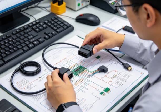
The vehicle-side connector is defined by SAE J1962: a 16-position DLC (Diagnostic Link Connector), Type A for 12 V passenger vehicles. Not every position is standardized, which is precisely why a pin-to-pin table matters more for OBD2 cables than for many other harness types.
|
Position |
Defined function |
Test relevance |
|
16 |
Battery power (+12 V, fused) |
Voltage rating, fuse protection, current capacity |
|
4 |
Chassis ground |
Continuity, bonding |
|
5 |
Signal ground |
Continuity, separation from chassis ground |
|
6 / 14 |
CAN High / CAN Low (ISO 15765-4) |
Twisted pair, impedance, shield-drain termination |
|
2 / 10 |
J1850 Bus+ / Bus− |
Present on US legacy vehicles, absent on others |
|
7 / 15 |
ISO 9141-2 / ISO 14230 K-Line and L-Line |
Signal integrity, wire gauge |
|
1, 3, 8, 9, 11–13 |
Manufacturer discretionary |
Must be documented, never assumed |
Positions 1, 3, 8, 9 and 11–13 are left to each vehicle manufacturer. A cable that bridges or repurposes one of these pins may work on one brand and damage equipment on another, so the pin map must be documented, not assumed.
Continuity and resistance. Every circuit should be verified pin-to-pin against the approved table, with a resistance limit per circuit. On K-Line and CAN circuits, excess resistance shows up as intermittent communication that a simple beep test will not catch.
Short-circuit and insulation testing. Adjacent positions in the J1962 connector are close together; a short between pin 16 (battery) and a signal pin can damage a scan tool. Hipot or insulation-resistance testing between circuits is standard practice for production lots.
Shield and drain verification. CAN and J1850 circuits rely on twisted-pair construction, often with a drain wire. The test plan should confirm shield coverage, drain termination point and isolation from signal circuits.
Power-path checks. Pin 16 carries vehicle battery power. The cable must be rated for it, fused where the design requires, and verified for correct polarity routing to the tool side.
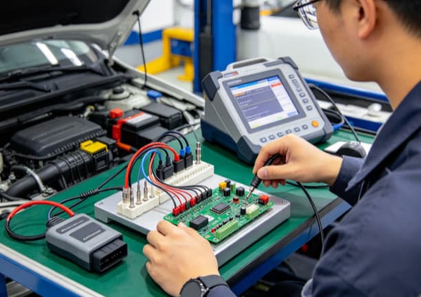
Electrical continuity does not guarantee communication. The protocol carried on those pins must also match the vehicle and the tool:
A buyer should state, per assembly, which protocols and which vehicle ranges (region, model year, 12 V vs 24 V systems) the cable must support. A J1939-to-OBD2 adapter, for example, must define exactly which J1962 pins carry the J1939 bus — a decision that varies between designs and must be traced to a drawing.
For OBD2 assemblies, a staged test plan is the practical baseline:
The functional step is the one most often skipped and the one that catches compatibility problems. Agreeing its scope before production — which protocols, which test equipment, which pass criteria — prevents disputes after delivery.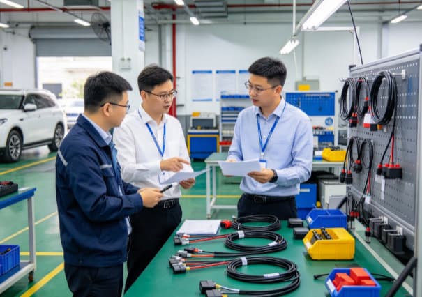
Continuity passes but the scan tool cannot connect. Why? Continuity only proves the electrical path exists. Communication also depends on resistance limits, twisted-pair and shield construction, correct pin usage and protocol match. Each needs its own verification.
Does one OBD2 cable work with all vehicles? No. The supported protocols, model years, regions and voltage systems (12 V vs 24 V) determine which vehicles the assembly can serve. This must be stated in the specification, not implied by the connector shape.
Are the non-standard J1962 pins important? Yes. Positions 1, 3, 8, 9 and 11–13 are manufacturer-discretionary. Their treatment in the cable must be documented and approved; bridging or repurposing them is a compatibility risk.
What functional evidence should a production lot include? As a baseline: 100% continuity and short-circuit testing, sampling insulation resistance, and functional protocol verification on the stated vehicle or simulator. The exact scope should be agreed at the RFQ stage.
Treat the pin map, the electrical tests and the protocol list as three separate checklists. Documented together with quantities and acceptance criteria, they turn an OBD2 diagnostic cable request into a specification a supplier can quote — and test — without assumptions. For a targeted review, submit the drawing or pin-to-pin table through the SOAR contact page.
[1] SAE J1962, Diagnostic Connector Equivalent — Electrical Signal Assignment.
[2] New York Vehicle Inspection Program, Diagnostic Link Connector.
[3] California Air Resources Board, OBD II systems fact sheet.


