

2026-10-22
When a check engine light illuminates, the diagnostic process begins at the 16-pin port located beneath the dashboard. An OBD (On-Board Diagnostics) diagnostic cable serves as the critical hardware bridge between the vehicle’s internal computer network and external diagnostic tools. While it may appear to be a simple wire, the engineering behind how an OBD diagnostic cable works involves complex electrical protocols and specific manufacturing standards designed to maintain signal integrity in harsh automotive environments.
Modern vehicles operate as a "network on wheels," utilizing dozens of Electronic Control Units (ECUs) to monitor everything from fuel injection to tire pressure. The diagnostic cable functions as the physical layer of this communication network. It translates the raw data from the vehicle’s Controller Area Network (CAN bus) into a format that a technician's scanner or software can interpret.
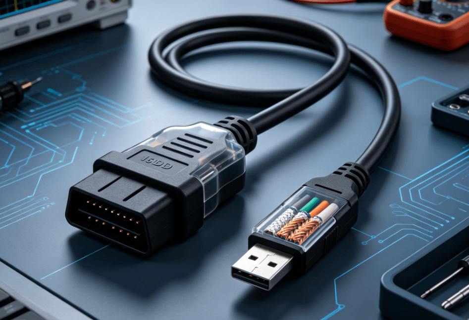
The fundamental role of an OBD diagnostic cable is to provide a secure, low-impedance path for data transmission. A standard cable consists of three primary sections: the male 16-pin connector (SAE J1962), the multi-core internal wiring, and the interface connector (typically USB, Serial, or a proprietary scanner head).
Inside the cable, specialized wiring is required to handle high-speed data. Unlike standard consumer electronics, automotive environments are prone to Electromagnetic Interference (EMI). To counter this, high-quality diagnostic cables utilize twisted-pair wiring for data lines. This design cancels out electromagnetic noise, ensuring that the signals sent from the ECU are not corrupted before reaching the diagnostic tool.
To understand how an OBD diagnostic cable works, one must look at the standardized pinout defined by the Society of Automotive Engineers (SAE). While the physical shape of the connector is universal for all cars sold in the US after 1996, the specific pins used can vary depending on the communication protocol.
| Pin Number | Function | Protocol/Standard |
|---|---|---|
| Pin 2 | Bus Positive Line | SAE J1850 (PWM/VPW) |
| Pin 4 | Chassis Ground | Standard |
| Pin 5 | Signal Ground | Standard |
| Pin 6 | CAN High | ISO 15765-4 / SAE J2284 |
| Pin 7 | K-Line | ISO 9141-2 / ISO 14230-4 |
| Pin 14 | CAN Low | ISO 15765-4 / SAE J2284 |
| Pin 16 | Battery Power (+12V) | Standard |
The cable's primary task is to establish a stable ground (Pins 4 and 5) and draw power (Pin 16) to wake up the diagnostic interface. Once powered, data flows through the designated communication pins, such as Pin 6 and Pin 14 for modern CAN-based systems.
The effectiveness of how an OBD diagnostic cable works is determined by its ability to support various communication protocols. The cable is essentially a "translator" for the following industry standards:
In professional-grade manufacturing, such as the assemblies found at Soar Cable’s automotive collections, these cables are engineered to meet specific impedance requirements. If the resistance in the wire is too high, the timing of the data packets can drift, leading to "link errors" during the diagnostic process.
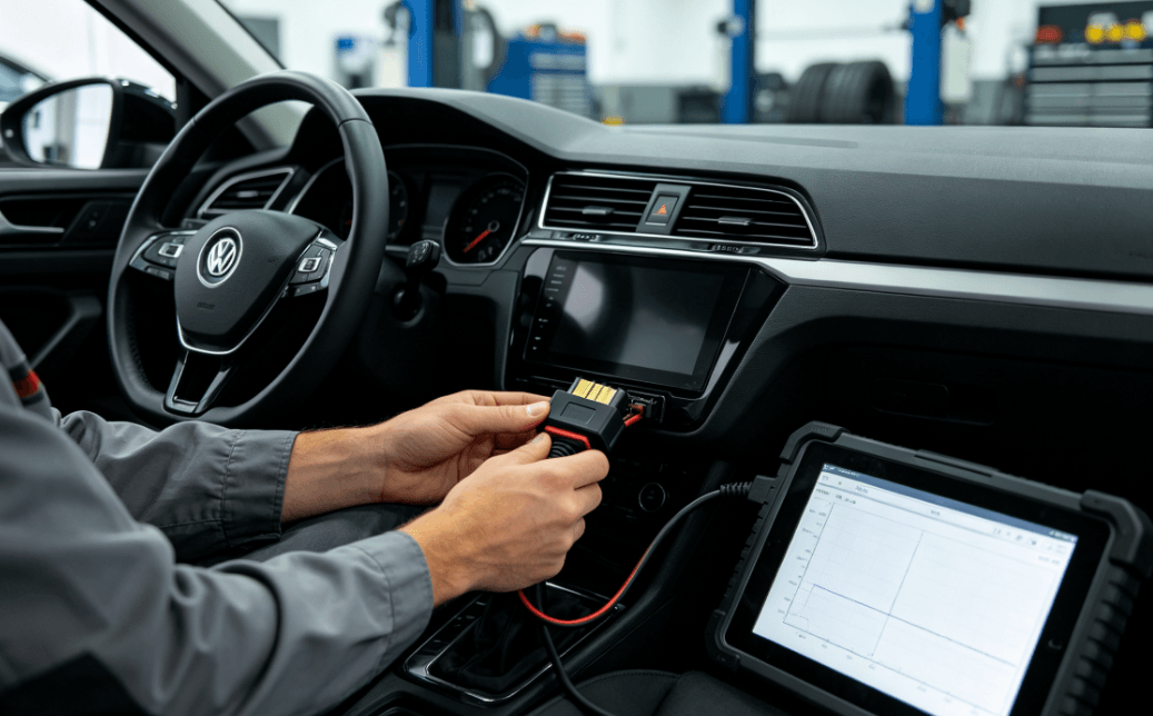
In a manufacturing context, the durability of an OBD cable is just as important as its electrical conductivity. Diagnostic cables in workshops undergo constant flexing, heat exposure, and contact with chemical solvents like oil or coolant.
Engineers focus on the "strain relief" at both ends of the cable to prevent internal wire breakage. Furthermore, the choice of jacketing material, such as TPU (Thermoplastic Polyurethane), is preferred for automotive use because it offers superior abrasion resistance compared to standard PVC.
Shielding is another critical factor. A high-quality OBD cable often features an aluminum-mylar foil shield and a tinned copper braid. This dual-layer shielding protects the data pins from the high-voltage spikes generated by the vehicle’s ignition system and alternator.
The way an OBD diagnostic cable works varies slightly depending on the application:
When selecting or designing a cable for these tasks, technical factors like wire gauge (typically 24 AWG to 28 AWG for data) and connector plating (gold or nickel) must be matched to the intended frequency of use.
Understanding how an OBD diagnostic cable works reveals that it is far more than a simple connector. It is a precision-engineered component that must manage power distribution, grounding, and high-speed data transmission simultaneously. For engineers and technicians, the difference between a successful repair and a communication failure often lies in the quality of the cable’s internal shielding and its adherence to international ISO standards.


