

2026-10-22
Medical cable assemblies are designed for the specific requirements of medical equipment, while standard cable assemblies are generally built for broader industrial, commercial or electronic applications. The main differences can involve materials, mechanical durability, shielding, sterilization compatibility, connector configuration, testing, documentation and application-specific requirements.
| Feature | Medical Cable Assembly | Standard Cable Assembly |
|---|---|---|
| Intended use | Medical equipment and healthcare applications | General industrial, commercial and electronic equipment |
| Design | Application-specific | General-purpose or standard configuration |
| Materials | Selected according to application and environmental requirements | Common cable materials for general applications |
| Sterilization | May require compatibility with specific sterilization methods | Usually not designed for repeated medical sterilization |
| Flexibility | Often designed for repeated movement and tight routing | Depends on the application |
| Shielding | May require controlled EMI/EMC performance | Application-dependent |
| Connectors | Often customized for specific medical equipment | Standard or semi-standard connectors are common |
| Testing | May include application-specific inspection and testing | Usually based on general product specifications |
| Traceability | May require detailed material and production records | Depends on supplier and application |
| Customization | Typically high | Low to moderate |
| Cost | Generally higher when customization and documentation are required | Usually lower for standard configurations |
medical cable vs standard cable should be treated as a defined engineering and procurement requirement, rather than as a generic product label. For medical-equipment interconnect and cable-assembly projects, cable and harness assemblies can appear similar while differing in connector keying, circuit count, signal logic, shielding, materials, branch layout, labels and required evidence. A buyer should therefore begin with the device interface, required materials, controlled drawings, risk-based supplier controls and verification evidence.
This article is written for a Commercial search intent. It provides an RFQ-oriented selection framework instead of making unverified promises about a particular configuration. SOAR publicly lists a medical cables collection and a SOAR testing equipment reference. These pages can help a buyer describe the product family of interest, but project-specific fit, performance and compliance remain subject to drawing review and RFQ confirmation.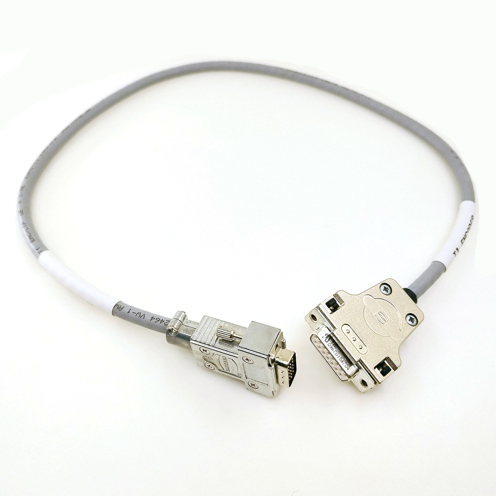
A keyword may identify a use case, product family or sourcing question, but it does not establish a finished configuration. For example, a request must still identify both mating interfaces, connector gender and coding, the intended electrical paths, target dimensions and installation conditions. It should also state whether the part is a prototype, a service adapter, a production assembly, an extension, a branch or a breakout. These facts determine what can be reviewed and quoted.
Independent engineering material supports the need for controlled workmanship and traceable definition. The ISO 13485 medical devices quality-management systems provides useful general background for this subject. Buyers may also use FDA overview of medical-device regulation to frame supplier-review or traceability questions. Neither source proves a particular supplier capability or product approval; the buyerâs controlled requirements remain the basis for selection.
| Requirement area | What to provide | Why the information matters |
|---|---|---|
| Application context | Equipment, vehicle, device or system; intended function; installation location | Sets the operating and configuration context |
| Interfaces | Approved connector part numbers, gender, coding, keying and acceptable alternatives | Prevents visually similar but incompatible connections |
| Electrical definition | Pin-to-pin table, signal names, power paths, shielding and grounding approach | Makes the circuit logic reviewable before manufacture |
| Mechanical design | Length, breakout dimensions, bend/routing limits, strain relief, jacket and labels | Defines installation and handling expectations |
| Verification | Required inspection, continuity, pinout, functional or documentation checks | Creates objective delivery-acceptance criteria |
Describe the intended system and the problem the assembly must solve. State whether it will carry power, data, analogue signals, diagnostic traffic, RF signals or a combination. If operation involves special environments, movement, repeated handling, a sealed enclosure or restricted routing, include those facts as controlled inputs rather than assumptions.
Requesters should provide controlled connector references whenever possible. Include mating geometry, gender, locks, keying, backshell or overmold expectations and allowable substitutes. A photograph may help communicate form factor, but cannot establish a pin assignment, coding or electrical requirement on its own.
Supply a pin-to-pin matrix and signal descriptions. Identify any power, ground, shield or drain paths and explain any Y-branch, breakout or pass-through function. For requirements involving diagnostics, RF, medical equipment or industrial control, compatibility must be confirmed against the actual system documentation and validation plan; it cannot be inferred from the keyword alone.
Specify the evidence expected at prototype and production stages. Depending on the application, it may include visual review, continuity checking, pinout verification, label inspection, dimensional inspection, functional testing or customer-defined tests. The required method, sample size and acceptance standard should be included in the RFQ or subsequent engineering agreement.
Commercial outcomes are configuration-specific. Cost, minimum order quantity and lead time may be affected by connector procurement, cable construction, circuit count, termination style, overmolding, branch complexity, documentation, inspection needs and quantity. These inputs should be reviewed in a quotation rather than presumed from a generic cable or harness name. A transparent RFQ separates prototype needs from recurring production requirements and identifies any approvals that could affect the schedule.
Buyers comparing offers should review the scope behind each price. A lower headline price can omit a specified connector, a test step, a label, a drawing revision or a documentation requirement. Asking suppliers to state assumptions and exceptions makes offers comparable and helps avoid a later scope change.
No. Listings and photos can be preliminary references, but the final decision should be based on controlled interfaces, electrical logic, dimensions and the applicable validation requirements.
Provide the application, both interfaces, a pin-to-pin requirement, lengths or mechanical dimensions, expected quantity and the desired inspection or test evidence. Flag unknown items for engineering review rather than leaving them implied.
No. Independent sources explain general terminology and selection considerations. Product compatibility requires confirmation against the exact vehicle, device, equipment or approved customer documentation.
Before prototype release or production authorization. The required evidence should be agreed with the design, quality and procurement stakeholders as part of the controlled project scope.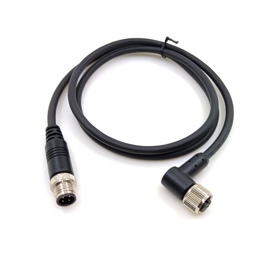
Use the medical cable vs standard cable topic as a structured starting point for an engineering-ready RFQ. When interfaces, electrical logic, mechanical construction and verification expectations are documented, buyers can request a targeted review and quotation without relying on generic assumptions.


