

2026-10-22
Automotive wire harness design sits at the center of vehicle performance, reliability, and manufacturability. For OEM applications, procurement teams, engineers, quality leaders, and distributors benefit from a shared framework to scope requirements, reduce risk, and accelerate sourcing without over-constraining the design.
Across platforms, OEM stakeholders expect traceable requirements, robust risk controls, clear change management, and feasible service strategies. Successful automotive wire harness design ties functional intent (signals, power, diagnostics) to installation constraints, environmental exposures, manufacturability, and serviceability, while keeping options open for platform variants. Establishing a common language for acceptance criteria early helps avoid costly rework and misalignment later in the program.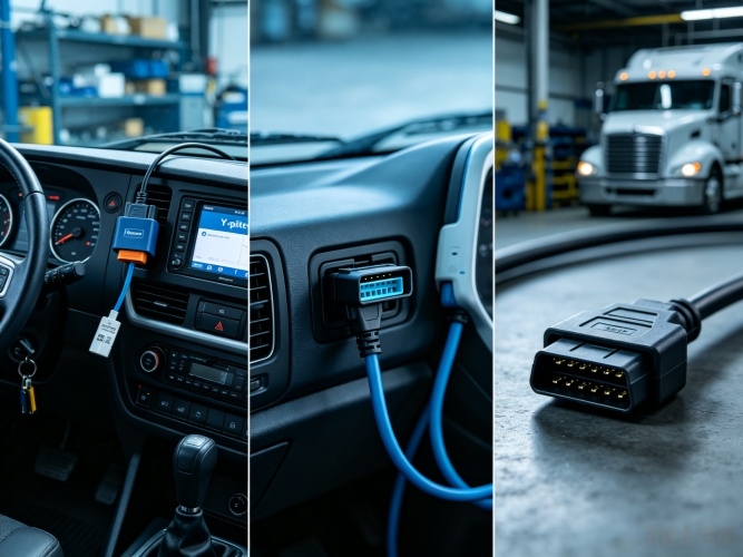
Begin by mapping functions to interfaces and environments. In automotive programs, harnesses often serve diagnostic, engine, and control cable applications. As examples, supplier collections show diagnostic and control harnesses with J1708/J1939, DB9, DB15, OBD-II, DT, and multi-interface diagnostic harness examples suitable for concept exploration. The SOAR Automotive Wire Harness Collection displays such examples for reference. Exact vehicle fitment, pinout, material selection, quality level, production quantity, lead time, and test evidence are order-specific (RFQ confirmation required) and cannot be inferred from examples.
For procurement and engineering teams, define the signal types, current paths, diagnostic protocols, and mating connector families before freezing the bill of design. Where multiple interfaces may exist on a single branch, clarify any de-pop/variant strategy and label controls. Keep the spec outcome-oriented: define functional needs and constraints, then let the harness partner propose manufacturable options during DFM reviews.
Electromagnetic compatibility planning influences braid/foil choices, shield termination, ground strategy, and connector backshell concepts. Shielding is not one-size-fits-all; it depends on EMI exposure, use conditions, and how shields are terminated and grounded, as noted in independent connector guidance [2]. In practice, align the EMC plan with critical signal integrity, ignition/actuator events, HV/LV proximity rules, and the vehicle’s ground reference scheme. Document how the shield continuity will be verified in manufacturing and service (approach only; specific test results are RFQ confirmation required). Early EMC cross-functional reviews reduce late-stage surprises.
Program teams should agree on workmanship criteria and product class at the outset. The widely used cable and wire harness assembly standard provides requirements and acceptance criteria for construction, soldering/crimping, insulation, routing, marking, and more; importantly, product class must be agreed by the stakeholders to set expectations [1]. Use that shared framework to inform drawings, visual aids, and sampling plans. Do not assume the collection examples define compliance for your order—any acceptance plan details and supporting evidence are RFQ confirmation required.
Automotive environments demand attention to abrasion paths, fluid exposure, temperature zones, vibration, and packaging constraints. Good practice pairs protective measures (sheathing, grommets, clips, strain relief) with routing rules, bend radii guidance, and service-clearance notes. Labeling and color conventions should support assembly and service while minimizing error risk. Where underhood or underbody exposure exists, specify environmental conditions and ingress considerations at the requirement level; concrete selections, sealing strategies, and component part numbers remain RFQ confirmation required.
Use the following decision matrix to compare potential build partners during sourcing. It emphasizes traceability, engineering collaboration, and manufacturability support over anecdotal claims.
| Criterion | Why it matters | What to ask at RFQ | Evidence to review |
|---|---|---|---|
| Requirements translation | Reduces redesign risk | How will you translate functional needs into drawings/BOM? | Sample redlines, draft drawing package |
| DFM/Value engineering | Improves yield and cost stability | What alternatives can maintain function while simplifying build? | DFM logs, change proposals |
| EMI/Shielding approach | Protects critical signals | How do you decide shield type and termination? | EMC review notes (test specifics are RFQ confirmation required) |
| Workmanship criteria | Defines acceptance upfront | Which acceptance criteria and product class will be used? | Quality plan referencing agreed criteria [1] |
| Traceability | Supports issue containment | What lot/trace methods are standard? | Example labels, traveler records |
| Change control | Prevents undocumented drift | How are ECNs and revalidation handled? | Sample ECN workflow |
| Serviceability | Reduces lifecycle cost | How are markings and access optimized? | Service guides, label maps |

Freeze only the problem statement and critical constraints early; keep the harness construct flexible through DFM. Lock drawings after cross-functional reviews covering acceptance criteria [1], EMC strategy [2], routing, labeling, and serviceability.
No. While examples such as J1708/J1939, DB9, DB15, OBD-II, DT, and multi-interface diagnostic harnesses are helpful for benchmarking, exact vehicle fitment and pinouts are order-specific and RFQ confirmation required.
Use the commonly referenced cable and wire harness assembly standard to establish requirements and acceptance criteria and to agree on the applicable product class among stakeholders [1]. Do not assume compliance without RFQ confirmation.
Base shielding decisions on EMI exposure, operational environment, and termination/grounding method, as outlined in independent technical guidance [2]. Specific validation details are RFQ confirmation required.
To explore diagnostic, engine, and control harness concepts, review SOAR’s automotive wire harness collection for example configurations. For background on capabilities and scope, see the SOAR company profile and stated automotive-cable scope. When your team is ready, share requirements for RFQ confirmation.


