

2026-10-22
Automotive wiring harness components—wires, terminals, connectors, and sleeves—form the backbone of vehicle electrical architecture. For procurement teams, engineers, quality leaders, OEMs, and distributors, aligning on component choices early reduces redesign risk, improves serviceability, and streamlines RFQs. This overview maps key decision factors, standards touchpoints, and supplier-qualification steps you can use across diagnostic, engine, and control cable applications, with order-specific details marked “RFQ confirmation required.”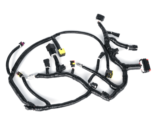
Automotive environments demand electrical continuity, mechanical robustness, and maintainability amid heat, vibration, fluids, and electromagnetic noise. Typical use cases include diagnostic, engine, and control cable applications (permitted scope). Representative diagnostic harness interfaces commonly seen on the market include J1708/J1939, DB9, DB15, OBD-II, DT, and multi-interface diagnostic harness examples. These visuals help teams discuss form and interface families, but any exact vehicle fitment, pinout, material selection, quality level, production quantity, lead time, or test evidence is RFQ confirmation required. Treat images and examples as starting points for your requirement set—not as proof of compatibility or performance for a particular order.
Wires: Conductor size, insulation type, and temperature rating are usually driven by current, routing, bend radii, fluids, and ambient conditions. Shielding and grounding strategies should be assessed against EMI profile and installation layout. Decisions must also consider how shields terminate and bond to reference ground to avoid unintended loops or insufficient coverage. See guidance that shielding choices depend on exposure, use conditions, and termination/grounding considerations [2].
Terminals: Crimp style, plating, and retention features influence electrical resistance and vibration robustness. Tooling, crimp-height validation, pull-force checks, and sample cross-sections are common quality gates (specific values are RFQ confirmation required). Mating terminal families also affect connector selection and service strategy.
Connectors: Sealed or unsealed; in-line or panel; keyed or color-coded; and interface standard (for example, a diagnostic receptacle vs. an underhood sensor plug) are primary decisions. Environmental sealing, polarization, and latching help ensure reliable mating under vibration and service operations. Vehicle-level maintainability may favor connector families with proven field handling and available accessories (caps, boots; RFQ confirmation required).
Sleeves and protection: Looms, braided sleeves, heat-shrink, and conduit reduce abrasion, manage noise (rattle/chafe), support bundling, and improve routing definition. Protection must not hinder heat dissipation or create moisture traps. Clip mounts, grommets, and strain-relief elements further stabilize the bundle (exact materials and ratings are RFQ confirmation required).
To minimize ambiguity, many buyers reference acceptance criteria from IPC/WHMA-A-620F. The standard outlines requirements and acceptance criteria for cable and wire harness assemblies, and explicitly requires agreement on the product’s class and applicable clauses between buyer and supplier [1]. In practice, teams should align early on:
Many issues in field returns trace back to misaligned protection strategies. For example, EMI-sensitive diagnostics or control lines near high-current paths may require shielded cable, with careful terminations to maintain shield integrity and avoid ground loops. Decisions should reflect exposure, use conditions, and the method of shield termination/grounding [2]. Likewise, underhood placements may call for enhanced sealing and abrasion protection, but routing should avoid sharp edges and allow service loops where needed. Each decision point below is order-specific and RFQ confirmation required.
Use the table to frame early discussions. Treat “Typical options” as families you may evaluate during sourcing; the final bill of materials, suppliers, and acceptance criteria are RFQ confirmation required.
| Component | Primary selection drivers | Typical options seen on market | Order-specific items (RFQ confirmation required) |
|---|---|---|---|
| Wires | Current/voltage, temperature, routing, EMI exposure | Unshielded or shielded; varied insulation families | Conductor size, insulation spec, shield style/termination |
| Terminals | Electrical resistance, vibration, mating family | Open/closed barrel crimps; plating variants | Crimp tooling, pull-force limits, inspection criteria |
| Connectors | Interface type, sealing, serviceability | Sealed/unsealed; in-line/panel; keyed variants | Pinout, cavity tooling, retention forces, marking |
| Sleeves/Protection | Abrasion, heat, fluid exposure, routing | Braid, heat-shrink, split loom, conduit | Material grade, wall thickness, clip/grommet choices |
| Test & Inspection | Continuity, polarity, workmanship acceptance | Continuity testers, visual criteria per buyer agreement | Test plan, sample size, acceptance class per [1] |
For a snapshot of market-ready harness examples oriented to automotive use—including diagnostic, engine, and control cable applications—see the SOAR automotive wire harness collection. It displays J1708/J1939, DB9, DB15, OBD-II, DT, and multi-interface diagnostic harness examples for discussion and planning. For capabilities context, review the SOAR company profile and stated automotive-cable scope. Any exact fitment, pinout, material, quality level, production quantity, lead time, or test evidence remains RFQ confirmation required.
Next step (non-coercive): share your draft drawing and acceptance criteria, request a feasibility review, and iterate to converge on manufacturable, testable specifications.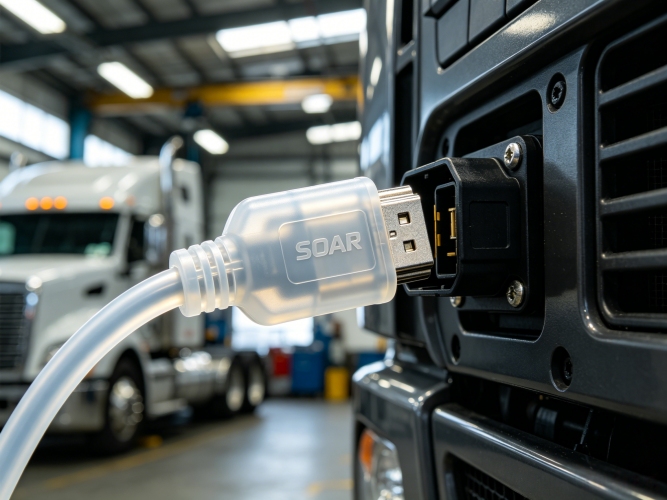
Map EMI sources and victim circuits, routing proximity, and grounding approach. Shielding decisions depend on EMI exposure, use conditions, and termination/grounding considerations; improper termination can negate benefits. See general guidance [2]. Final calls are RFQ confirmation required.
Many teams reference IPC/WHMA-A-620F for cable and wire harness assemblies. The standard provides requirements and acceptance criteria, but buyer and supplier must agree the applicable product class and clauses [1]. Document agreements in the RFQ and PO.
No. Displayed harnesses are examples for planning. Exact vehicle fitment, pinout, material, quality level, production quantity, lead time, and test evidence require RFQ confirmation. Provide your drawing, pin map, and acceptance criteria for a definitive quote.
Provide drawing with wire IDs and colors, lengths, pinout, connector part numbers, labels, protective elements, target product class and acceptance clauses, and a proposed test plan. Any numeric limits or validation evidence are RFQ confirmation required.


