

2026-10-22
In the high-precision world of automotive engineering, data is as critical as hardware. The OBD connector cable serves as the primary gateway between a vehicle's internal nervous system and external analytical tools. While many car owners recognize the 16-pin port under their dashboard, the technical utility of the cable assembly extends far beyond simply clearing a "Check Engine" light. For professionals in manufacturing, fleet management, and diagnostics, this cable is a precision instrument designed to handle high-speed data protocols and maintain signal integrity in harsh electrical environments.
The modern OBD (On-Board Diagnostics) connector cable is a specialized wiring assembly that facilitates communication between the vehicle’s Electronic Control Units (ECUs) and diagnostic hardware. From a manufacturing perspective, these cables must adhere to strict international standards to ensure they don't just "fit," but also function reliably under the electromagnetic interference (EMI) typical of a running engine.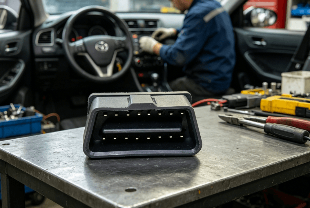
To appreciate what an OBD connector cable is used for, one must understand its standardization history. Before the mid-1990s, the automotive industry was fragmented, with manufacturers utilizing proprietary connectors and protocols. This made universal diagnostics nearly impossible for independent repair shops and fleet managers.
The transition to the OBD-II standard, specifically the SAE J1962 specification, revolutionized the industry. Today, a professional-grade OBD connector cable uses this standardized 16-pin interface to provide a universal link. This allows a single diagnostic tool to communicate with diverse vehicle makes, from passenger cars to light-duty trucks. However, while the physical shape is standardized, the internal wiring and material quality can vary significantly between consumer-grade accessories and industrial-grade automotive wire harnesses.
The core utility of an OBD connector cable is its ability to "translate" the complex electrical signals of a car's Controller Area Network (CAN bus) into a format that software can interpret. This involves several critical functions:
The most common use for an OBD connector cable is the retrieval of DTCs. When a vehicle's onboard sensors detect a parameter outside of its normal operating range—such as an O2 sensor reading too lean or a cylinder misfire—the ECU stores a five-digit code. The cable provides the physical pathway for a scan tool to request these codes, allowing technicians to pinpoint the source of a malfunction without manual disassembly.
Beyond error codes, the cable facilitates "Live Data" streaming. This is used by engineers to monitor engine RPM, ignition timing, fuel trim, and mass air flow in real-time. In a professional diagnostic setting, this data must be transmitted with zero latency, which requires high-quality copper conductors and precision-crimped connectors to prevent signal dropouts.
In many jurisdictions, vehicle registration requires an emissions test. The OBD connector cable is used by state inspectors to check the status of the vehicle’s "Readiness Monitors." These are internal self-tests the car runs on its catalytic converter, EVAP system, and oxygen sensors. The cable verifies that these monitors have "Passed" or "Completed" without needing a traditional tailpipe sniff test.
The 16-pin layout is the DNA of the OBD connector cable. Each pin is assigned a specific role, though some are left to the discretion of the manufacturer for proprietary features.
| Pin Number | Assignment | Function |
|---|---|---|
| Pin 2 | SAE J1850 Bus+ | Used for older American vehicles (PWM/VPW). |
| Pin 4 | Chassis Ground | Ensures electrical safety and common reference. |
| Pin 5 | Signal Ground | Dedicated ground for sensitive data signals. |
| Pin 6 | CAN High (ISO 15765-4) | High-speed data communication (modern standard). |
| Pin 7 | K-Line (ISO 9141-2) | Communication line for older European/Asian models. |
| Pin 14 | CAN Low (ISO 15765-4) | Complements Pin 6 for differential signaling. |
| Pin 16 | Battery Power | Provides +12V power to the diagnostic tool. |
Professional-grade cables ensure that pins 6 and 14 (the CAN bus lines) are structured as a twisted pair. This is a critical manufacturing detail that reduces electromagnetic noise, which is essential for maintaining data integrity during high-speed communication.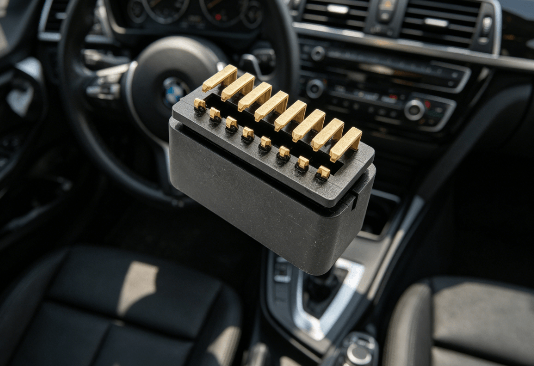
For businesses, the OBD connector cable is more than a repair tool; it is a component of larger integrated systems.
Fleet operators utilize OBD cables to connect telematics devices that track vehicle location, driver behavior, and fuel efficiency. In this scenario, the cable is often part of a "Y-splitter" or an "under-dash bypass" harness. This allows the telematics device to remain hidden and permanently connected while leaving the factory OBD port open for service technicians.
In the automotive aftermarket and performance tuning sectors, the OBD connector cable is used to overwrite the factory software on an ECU. This process, known as "flashing," requires a rock-solid physical connection. A momentary loss of contact due to a loose terminal or poor cable quality can "brick" an ECU, rendering the vehicle inoperable and resulting in thousands of dollars in damages.
Insurance companies deploy small "dongles" that interface via the OBD connector. These devices collect data on braking intensity and mileage. For manufacturers of these devices, sourcing a cable with a low-profile connector is vital to ensure it does not interfere with the driver's legs or the vehicle's interior trim.
From an engineering standpoint, an OBD connector cable must be built to survive the "automotive environment." This includes resistance to extreme temperatures, vibration, and chemical exposure (such as oil or coolant).
In a vehicle, high-voltage ignition systems and alternators generate significant electromagnetic noise. If an OBD cable is unshielded, this noise can corrupt the data packets being sent from the ECU to the diagnostic tool. High-quality cables use Aluminum Mylar shielding or tinned copper braiding to protect the internal data lines.
The pins inside the connector are subject to "fretting corrosion" due to vehicle vibration. Professional-grade cables use phosphor bronze or copper alloy terminals, often plated with gold or high-quality nickel, to ensure a low-resistance connection over the lifespan of the tool.
In heavy-duty workshop use, cables are frequently pulled and twisted. A molded strain relief at the connector head prevents the internal solder joints or crimps from fatiguing. This is a hallmark of industrial connector design that separates professional tools from cheap consumer alternatives.
When sourcing OBD connector cables for OEM projects or diagnostic tool manufacturing, several factors must be evaluated:
By focusing on these technical nuances, engineers can ensure that their diagnostic hardware provides accurate readings every time, reducing troubleshooting time and improving overall vehicle reliability.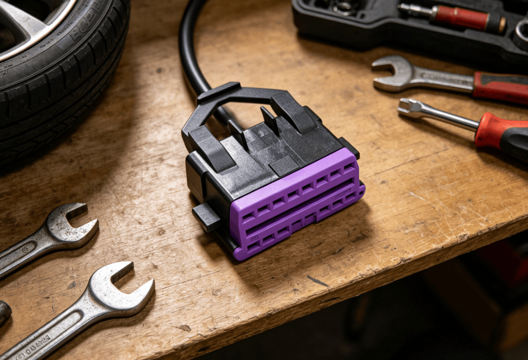
The OBD connector cable is the indispensable link in modern vehicle maintenance and data acquisition. Its utility spans from basic error code retrieval and emissions testing to complex fleet telematics and ECU recalibration. By adhering to the SAE J1962 standard, it provides a universal language for vehicle communication. However, for professional and industrial applications, the value of the cable lies in its manufacturing integrity—including signal shielding, terminal plating, and environmental durability. Choosing a high-quality cable assembly is not just a matter of connectivity; it is a safeguard for the sensitive data that drives the modern automotive industry.
Most passenger vehicles manufactured after 1996 in the United States and 2001 in Europe use the standard 16-pin OBD-II interface. However, heavy-duty commercial vehicles and some motorcycles may use different standards, such as the J1939 9-pin Deutsch connector.
Yes, the primary differences are in shielding and terminal quality. Professional cables utilize shielded twisted pairs for CAN lines to prevent data corruption from engine noise, while cheaper cables may use unshielded, thinner gauge wire that leads to communication errors.
Yes, Pin 16 of the standardized OBD-II connector provides a constant +12V from the vehicle's battery. This allows diagnostic scanners and telematics devices to function without an external power source or battery.
While rare, a poorly manufactured cable with internal shorts or incorrect pin-outs can potentially damage the vehicle's Gateway Module or ECU. It is essential to use cables from reputable manufacturers that follow strict quality control standards.
Length is often determined by the application. Handheld scan tools typically use 1.5-meter to 3-meter cables for ergonomics, while telematics bypass harnesses are much shorter (15cm to 30cm) to allow for concealed installation behind the dashboard.


